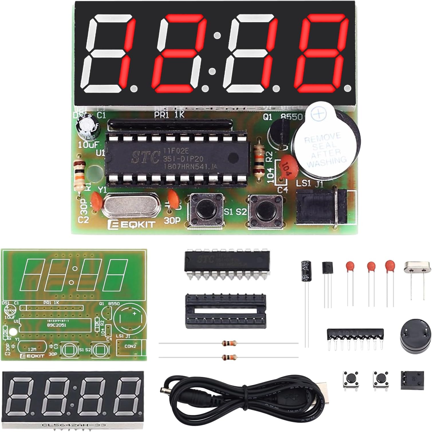


Buy anything from 5,000+ international stores. One checkout price. No surprise fees. Join 2M+ shoppers on Desertcart.
Desertcart purchases this item on your behalf and handles shipping, customs, and support to Iceland.
⏳ Build Your Time, One Solder at a Time!
The MiOYOOW 4-Digit Digital Clock Kit is a DIY electronics project designed for students aged 13 and above. It features a user-friendly assembly process, accurate timekeeping, and dual alarm settings, making it an excellent educational tool for learning soldering and electronic principles.


| ASIN | B0711MHKDZ |
| Age Range Description | over 13 years old |
| Battery Description | No Battery |
| Best Sellers Rank | #22,453 in Tools & Home Improvement ( See Top 100 in Tools & Home Improvement ) #16 in Clock Hardware |
| Brand Name | MiOYOOW |
| Customer Reviews | 4.2 out of 5 stars 886 Reviews |
| Educational Objective | STEM |
| Included Components | electronic cpmponents |
| Is Assembly Required | Yes |
| Item Dimensions | 3.5 x 2.6 x 0.7 inches |
| Item Weight | 0.05 Pounds |
| Manufacturer | WHDTS |
| Manufacturer Minimum Age (MONTHS) | 156.00 |
| Manufacturer Part Number | 1765 |
| Material Type | Copper |
| Model Number | 1765 |
| Size | 2.6 x 3.5 x 0.7 inches |
| Theme | Science Fiction |
| UPC | 615135207189 |
| Unit Count | 1 Count |
C**T
The best electronics kit on Amazon - make this in ten minutes! LEARN ELECTRONICS - here is how!
This is a great kit to learn about electronics. Of all the kits available on Amazon this one is most likely the best for learning. It also ends up with a great clock. I have built three of them so that for my day job I can track my employees who are in different time zones. If you are looking for a way to learn about electronics, a way to learn about soldering, a great alarm clock that you can be proud to have built – THIS is the kit to purchase. It is the best one on Amazon. Look no further! I am using this in my university courses to get students exposed to circuit components and construction. Here is a portion of my lab assignment for this project that might help you build it. Tools Make sure you have a • Soldering Iron • Solder • Small wire clippers • Optional – a silicon work mat (so you wont burn the surface you are working on) Here are ways to make your project NOT work. • Inserting certain components with the wrong polarity (in the wrong direction). • Cold solder joints. • Missing a solder connection. • Solder bridges (inadvertently connecting two solder pads on the back of the PCB). • Not inserting the power barrel connector all the way in. Layout the parts in the order that they will be installed. Build • Insert the two resistors and bend the leads to hold the resistors in place. They can be placed in any direction as resistors do not have polarity. • Install the two 30 pf ceramic capacitors and bend the leads to hold the capacitors in place. Make sure you put the right capacitors in the right locations. • Install the 104 pf ceramic capacitor and bend the leads to hold the capacitor in place. Make sure you put the right capacitor in the right location. • Install the 12 MHz crystal oscillator and bend the leads to hold the oscillator in place. • Solder all the leads to the PCB board. Remember to heat the board and the wire and not the solder. The solder will flow when the PCB connection and wire are hot enough. The connection should be shiny if a good solder connection has been made. • Clip all the leads. • Install the network resistor. The network resistor must be installed with the dot aligned with the mark on the PCB board. • Solder the network resistor’s nine pins. • Insert the DIP-20 IC socket. The DIP-20 IC socket must be installed with the notch aligned with the printed notch on the PCB. • Solder the 20 pins. • Insert the transistor. The transistor must be installed with the flat side of the transistor aligned with the flat side printed on the PCB. Bend the leads to hold the transistor in place. • Solder the three leads. • Clip the three leads. • Insert the two button switches. If they aren’t going easily in they are most likely being installed incorrectly. • Solder the eight pins. • Install the 10 uF 25V electrolytic capacitor. Electrolytic capacitors have polarity. The shorter leg goes into the shaded area on the PCB. Bend the leads to hold it on place. • Solder the leads. • Clip the leads. • Install the power socket. • Solder the three pins. These pins are close. Make sure there aren’t any solder bridges. • Install the buzzer. The buzzer has polarity. Insert the longer lead into the hold marked with a + on the PCB. • Solder the leads. • Clip the leads. • Insert the 4-bit display. Make sure there isn’t any Styrofoam on the leads. The display has polarity. Make sure the decimal points are toward the other components. The pins might need slight adjustment to fit into the holes. • Solder the ten pins. • Clip the pins. • Insert the IC making sure that the notch in the chip are aligned with the notch on the socket. Check that the pins are aligned with the sockets before pressing the chip firmly in place. • Remove the white sticker from the buzzer for a louder sound – it’s really loud with it off. • Plug the power cord into USB power and then plug the barrel connector into the clock. The connection is firm and might not be fully in place. If the clock turns off when you take your hand off the power cords then it wasn’t fully inserted. Consider covering the back with tape – like blue painters’ tape – to prevent shorting out the clock. Remember too, there aren’t any memory components so when power is removed and then reapplied the clock will reset back to 12:59. All in all, this project can be completed in fifteen minutes or less!
A**R
Easiest kit I ever assembled.
Perfect kit for beginner. Very low part count, can be assembled in less than an hour. The board is well made with parts symbols and value clearly printed for correct placement. The step by step instruction with picture is easy to follow. My finish clock works right away after I assembled it and powered it up for the first time. I was a bit concerned when I noticed the colon in the display is flashing on and off too slowly, however, the colon was designed to flash on every other second, other than that, the clock is keeping time just fine. One minor last step that was not mentioned in the instruction is: you would want to use a short piece of wire to strap down the power jack, insert the two ends of the wire into the two holes on both sides of the jack on the circuit board then solder the wire. You can see this wire on the power jack in the last picture of the instruction manual and it look bare. However, I would only strip the insulation at the end of the wire, pull and hold the two ends of the wire tightly on the other side of the circuit board to provide some hold down force on the jack then solder the wire to the circuit board. On the setting instruction of the clock, there are several place that say: "Short press S2 to save the adjusted results and quit .." but the switch should be S1. I'm impressed that the designer can cram many operational features into this clock kit. One more feature I would love to see (maybe in a new version?) is a setting for the clock to adjust itself automatically. Many years ago, I had a quartz digital watch that has a such a setting: to tell the watch to compensate itself for the obvious steady gain or loss of seconds within a certain time frame,
J**E
Great product if you follow directions
This is my very first soldering project. What i did before i watch youtube videos on soldering was not soldering. This kit was awesome. User error always affects success. I soldered the 140 ceramic capacitor in the wrong place and the thing would not turn on. I used a rosin coated braid to desolder the capacitors and then re-solder them in the correct positions on the board, which btw, is labeled on the board and in the pictures and diagrams. Once i did that, it works just fine. The programing notes are a little wonky fir the alarms but i just turned everything off. Leave the white paper over the buzzer unless you want to go crazy cuz it is loud....until you program it. Love it...i am no expert.
E**.
Great project for soldering beginners
I am currently working on soldering some guitar pedals, but had never soldered anything beyond a few simple wires. This project was EXACTLY what I needed. It gives you the full range of soldering experience in a nice tight little cheap kit. I was extremely proud when I got the thing to turn on and have the buttons work. Is this kit easy? No, I wouldn't say that. The instructions are fine. What this kit does, however, is prepare to do soldering on standard sized PCBs. Some of the connections are pretty close together so you need to get your soldering good and accurate (to avoid crossing connections). You will almost certainly make mistakes. If you are good at soldering, this is easy. But this is geared towards beginners but it's not an EASY option, but a realistic one. Note for other beginners: You'll want a soldering iron and solder (duh) but you'll also want solder wick. The wick is used to help soak up solder when you make mistakes. I definitely made a bunch of mistakes that I had to undo ,and this board gave a good place to practice. Another note for beginners: I soldered the components onto the board in height order (shortest first).
A**I
Good practice; shame it didn't function in the end
I built it. Unfortunately, the clock didn't work when plugged in. It would just make this screeching banshee noise that died out eventually, and the segmented display lit up random segments. Either my noob soldering fault or...? Despite this, it was a good practice for soldering; might buy another one to try again and hopefully it'll work! (hint: google the instructions before hand. I did some soldering steps out of step with the document I found online for this product; may be why it malfunctioned)
B**L
A very nice beginner kit that goes together easily and works very well!
I bought this kit as a father-son project. He is a typical teenager – loves technology and is very curious to know how things are built and how they work. We were both really excited to receive this kit. The kit was shipped to us in a padded envelope and arrived on-time in perfect shape. As shown in the photo, it came packed in a small cardboard box. The box is a great place to store the components as you put the clock together. On the day the kit arrived, I was very impressed to receive an e-mail from the seller with a link to a PDF instruction manual. The manual contains assembly instructions, a parts list, operation instructions, and a schematic. The assembly instructions were clear with good photos, and because the schematic was included, I was able to trace thru how the clock works with my son. The clock is well designed – it’s based around an STC11F02E microcontroller that is clocked by a 12 MHz crystal. The display is a 4-digit LED display and includes a proper voltage dropping resistor array to ensure that the LED display is run within its maximum ratings. The board runs off of a +5VDC supply and includes proper filtering and bypass capacitors. The PCB and the parts in the kit are of good quality – all of the components went onto the PCB with no issues and the board was very easy to solder. My son did most of the soldering himself and he’s rather new to soldering. This board would be a very good kit to hone your soldering skills if you are a beginner at soldering. The assembled clock powered up successfully the first time and is working great! We were able to set the time and turn the alarms on and off without any problem. So far, it is keeping good time, neither losing nor gaining any time in the three days it has been powered on. The alarm is quite loud, so if you wanted to, you could use this as your main alarm clock. Bottom line, this is a well-designed, well-produced kit that is well suited for a beginner in assembling and soldering kits. We found it to be an excellent value. I highly recommend it.
S**B
Some soldering already done, board damage, missing power cable and no instructions.
I received a kit that had been returned by another customer who made a poor attempt at assembly. Some of the parts where already soldered to the board (some of the worst soldering work I have seen in 40 years). one 30pf cap already on the board with a lead missing and the solder pad torn off the board. Instructions missing, no Qr code and NO POWER CORD. I do have advanced electronic skills and I was able to repair the prior work, replace the bad cap and complete the kit, it's working. But I Still need a power cord and instructions for how to set it would have been nice. If someone sends me what I paid for I would update the review.
A**N
Great Clock Kit to Build
First, I like Clocks. I have many in my collection and I wanted to see what a <$10 kit would be like. Overall, this is a great kit that was easy to build (solder) and works well. There are only a few discrete parts, the circuit board is clearly marked, the solder mask is of high quality, and I found no mistakes or errors in the circuit. It went together in about 45 minutes and has been reliably clocking time since I powered it up. As of this review, it has been running for 24 hours so I can’t yet say how accurate it is. However, it is based off a 12 MHz clock with digital circuitry so I expect it to be reasonably accurate. The instructions packed in the kit are in English & WHDTS emailed a 9-page manual (PDF) a day after the kit arrived which details both the build steps & how to operate the setting functions. If you use the detail PDF, be aware that page 4 shows a circuit board that is not the clock kit. I think page 4 was meant to show the orientation of part #5, the PR1 Network Resistor, which must be installed with the Dot next to the square box (to the left as viewed from the front) on the circuit board. If this part is in backwards, the clock probably won’t operate. The photo on page 5 is correct. I think someone just inserted the wrong picture on page 4. As a somewhat experienced kit builder, I was pleasantly surprised to see they included a socket for the main integrated circuit chip. Many inexpensive kits omit a socket which means any debugging or part placement checking is more difficult. A few of the parts must be installed in a specific orientation so look at the photos, the parts, and double check your placement before soldering. One final thought. The clock and alarm setting steps are fairly long since you have the main time and two alarms. Read the steps thoroughly and be prepared to start over if you make a procedural error. After a couple tries, it can be set easily but the 1st time through might be confusing. The designers thoughtfully made the clock show which menu step you are in as there are 10 or 11 steps to follow.
J**.
La peor compra realizada
El artículo está incompleto, es difícil armarlo, ya que no tiene instructivos ni videos de armado… la relación precio-calidad es pésima. Ojalá que me devuelvane mi dinero
P**L
bon ti projets
facile à monter ..et le fun a faire...fonctionne très bien...jai juste arrache les petit speaker...c'était fatigant
B**P
not good product
not good product
M**Y
Good product
Good product. Clear and simple. Perfect for a beginner in either soldering or electronics.
D**N
Très satisfait.
Très satisfait comme tout mes achats chez Amazone ces temps-ci. Merci amazone.
Trustpilot
2 weeks ago
2 weeks ago